Three Different Meanings of Temperature
| Temperature | Meaning | Example |
|---|---|---|
| Physical, | Actual hardware temperature; a thermometer could measure it | 290 K |
| Equivalent noise, | Receiver-added noise expressed as an equivalent input temperature | 50 K |
| Reference, | The fixed convention for defining noise factor and noise figure | Always 290 K |
- One receiver can have 290 K hardware, 50 K equivalent noise, and a 290 K reference
- is what noise figure is defined against
Equivalent Noise Temperature
- A useful way to describe added noise:
- Noise arrives: the receiver amplifies the incoming noise
- The receiver adds noise: the output contains both contributions
- Express that addition at the input: is the strength of an equivalent thermal source
- Two models, exactly the same output:
- Actual receiver: input signal + source noise → physical receiver (gain , adds noise) → output signal + total noise
- Equivalent calculation model: same input + equivalent added density → noiseless amplifier (same gain ) → same output signal and noise
- We relocate the added noise in the model; the hardware and its output are unchanged
- From a noise figure: (NF ↔ Tₑ)
Which Noise Contribution Matters Most?
- System noise temperature = source (antenna) noise + receiver-added noise:
Same Receiver, Two Sources
- Same receiver: NF = 0.69 dB; convert once: (Ref: JPL DESCANSO Vol. 10, Ch. 2)
Source Larger part Cold sky, 30 K 80 K 19.0 dB-K Receiver noise Room temperature, 290 K 340 K 25.3 dB-K Source noise
- Lowering receiver noise helps most when receiver noise dominates
- Antenna noise need not be 290 K: lower antenna noise gives lower total noise with the same receiver NF
Reference Planes in the Receiving System
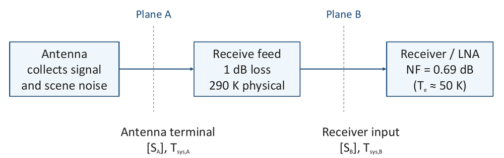
- Plane A (antenna terminal): ,
- Plane B (receiver input): ,
WARNING
- Use signal and total equivalent noise at the same plane
Feed Loss and Noise at Two Planes
- A room-temperature feed: 1.0 dB loss, 290 K physical; linear loss
- At A (feed input): antenna noise 30 K, signal
- At B (feed output): signal dB, antenna noise
- The feed’s own thermal noise:
- Referred to input A:
- Delivered at output B:
- Both terms represent the same feed noise at different planes
One System, Two Noise Ledgers
System Noise Temperature with a Lossy Feed
Lunar Link Noise Ledger
Contribution At A: before feed At B: after feed Antenna 30.0 K 23.8 K Feed emission 75.1 K 59.6 K Receiver 63.0 K 50.0 K 168.0 K 133.5 K 22.3 dB-K 21.3 dB-K
- A to B: and both fall 1.0 dB, so S/N₀ stays unchanged
- The receiver term at A is ; this slide rounds it to 63.0 K, the later system-noise slide shows 62.9 K
What Attenuates Signal? What Adds Noise?
| Mechanism | Signal | Noise |
|---|---|---|
| Free space, pointing, polarization mismatch | Less received power | No thermal emission implied by this loss |
| Room-temperature feed / absorbing atmosphere | Attenuated | Incoming noise attenuated; thermal emission added |
| Receiver amplifier | Amplified | Incoming noise amplified; receiver noise added |
- The absorbing-atmosphere case: loss and emission
Lunar Link: Reference Planes
| Quantity | Antenna terminals A | LNA input B |
|---|---|---|
| Received signal | −131.9 dBW | −132.9 dBW |
| Equivalent system temperature | 168.0 K / 22.3 dBK | 133.5 K / 21.3 dBK |
| Equivalent noise density | −206.3 dBW/Hz | −207.3 dBW/Hz |
| S/N₀ | 74.5 dB-Hz | 74.5 dB-Hz |
- Same complete system represented at two planes; B includes receiver-added noise referred to its input
WARNING
- Moving the bookkeeping plane changes nothing, but physically inserting a lossy cable still degrades the link (LNA placement)