Why Put Information on a Carrier?
- Information (bit levels) × carrier (fixed frequency ) in a modulator → RF output whose phase carries the bits
- The data selects the carrier phase (illustrative BPSK; only a few RF cycles per bit drawn)
- The antenna radiates the RF output
- Low-rate information moves to a band suited to antennas and spectrum allocation (bands and spectrum)
- The bits themselves first become a baseband waveform: Bits, Symbols, and Line Coding
On-Off Keying
- OOK: one state sends a carrier, the other sends no carrier
- The information changes the carrier amplitude
- For unbalanced on/off levels, a residual carrier component may remain
Frequency-Shift Keying
- FSK: a 0 and a 1 select different carrier frequencies
- The receiver decides which tone is present
- Required bandwidth depends on tone spacing and pulse shaping
BPSK: A Bit Selects the Carrier Phase
- BPSK (binary phase-shift keying): two phases separated by 180°
- One bit per modulation symbol
- For rectangular bit pulses, the null-to-null RF bandwidth is approximately (RF bandwidth)
- Constellation: the symbol states after carrier removal
- I = in-phase (horizontal axis), Q = quadrature (vertical), relative to the carrier reference
- Ideal BPSK: two values (±) and ; each point is one possible symbol
QPSK: Two Bits per Symbol
- QPSK (quadrature phase-shift keying): four carrier phases represent four possible two-bit symbols
- Constellation: one point in each quadrant
- Each transmitted symbol carries two bits
- For an uncoded QPSK link: (bit rate and symbol rate)
Summary: Amplitude, Frequency, and Phase
- The same data (1 0 1 1 0 0 1 0) controls each carrier:
- ASK: amplitude changes with the bit
- FSK: frequency changes with the bit
- BPSK: phase changes with the bit
- Adjacent equal bits need no state change
The I and Q View of a Modulator
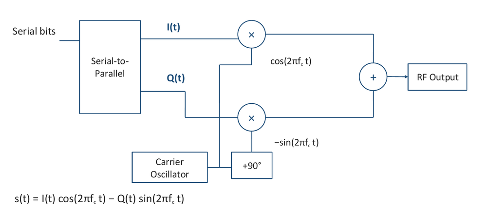
- Serial bits → serial-to-parallel → and
- Carrier oscillator → on the branch; +90° shift → on the branch
- Multiply, then sum → RF output
I/Q Modulator Output
Question: BPSK or QPSK?
- Uncoded information rate = 1.0 Mbit/s. Keep received power, noise density, and pulse shaping fixed. Change BPSK to QPSK. Which statement is correct?
- Symbol rate halves, so the RF bandwidth is about halved
- The received energy per information bit doubles
- The symbol rate doubles
- Answer: 1 — half the symbol rate and RF bandwidth
- : BPSK 1.0 Msymbol/s; QPSK 0.5 Msymbol/s
- 2 is false: fixed power and information rate give the same energy per bit
- 3 is false: symbol rate halves
- At a fixed symbol rate instead, QPSK carries twice as many information bits per second
NOTE
- So QPSK saves bandwidth, not power: it cannot rescue a power-limited link (the 4 Mbit/s question)
Higher-Order Constellations
- M-PSK places more phase states on a circle; QAM (quadrature amplitude modulation) uses amplitude and phase (e.g. a 4 × 4 grid of 16 states)
- More coded bits per symbol can reduce the required symbol rate
- At fixed average symbol energy, more closely spaced states are harder to distinguish
- Envelope variation and amplifier linearity become important
Modulation Selection Is a Mission Trade
| Need | Signal design implication |
|---|---|
| Weak signal acquisition | Consider tracking aids and residual-carrier power |
| High data rate in limited spectrum | More bits per symbol and appropriate pulse shaping |
| Efficient spacecraft power amplifier | Control envelope variation and amplifier backoff |
| Navigation or tracking on the same link | Allocate signal power and spectrum to each function |
- Choose the waveform with the receiver, amplifier, and mission requirements in view
- Related: pulse-shaping costs, residual carrier and power allocation
Analog Modulation
- Optional reference slide; message , carrier amplitude :
- FM bandwidth, Carson’s approximation:
- No blanket AM/FM/PM performance ranking applies without assumptions
- References: Gallager, MIT 6.450 Ch. 6 (Channels, Modulation, and Demodulation); Keysight AN 1298 (Digital Modulation in Communications Systems)